Project Grave Digger: Almost Ready to Roll
Completing the rolling and steering setups of my Grave Digger power wheels
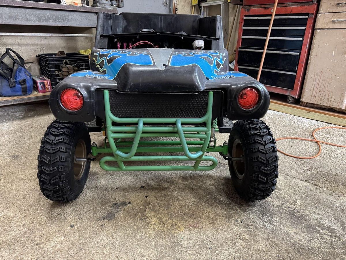
With the back wheels sorted out it was time to turn my attention to the front wheels. I expected I was going to have to fabricate an entirely new steering arrangement to use the new wheels but fortune was on my side and Grave Digger’s stock spindles were the same 12mm diameter as the Razor ATV bearings. Combined with some 50mm aluminum spacers from McMaster Carr the new front wheels bolted right up.
The 50mm spacers pushed the front wheels out the perfect amount to match the width I decided to go with in the rear. With the final wheel dimensions all set I spent time finalizing the rear axle. This involved cutting the 1000mm axle to its final length and drilling 6mm through holes for the wheel mounts, drive sprocket and disc brake. The drive sprocket and disk brake were keyed to the Razor ATV axle shaft however, the keyway size was different between the stock Razor ATV parts and the new axle I bought so I took the easy route and just used through bolts to lock everything in place. The Razor ATV uses through bolts for the wheel mounts from the factory, so I expect this to be fine, if these bolts ever fail I can always buy another axle and pursue the use of keys instead.

With all 4 wheels mounted I was finally able to get a true profile shot.

The final safety piece I wanted to put in place was a brake. The original wiring in Grave Digger combined with the motor resistance would naturally apply a brake when you took your foot off the accelerator pedal. Now that Grave Digger is heavier and there is no electric brake I wanted to take advantage of the disc brake that comes on the Razor ATV axle.
There is minimal space in the footwell of a child’s power wheel (citation needed) and because the body of Grave Digger is all plastic, there aren’t any stiff or secure mounting points I could take advantage of. After some thought I realized I could reuse the Razor ATV’s hand brake and mount it to the floor next to the new accelerator pedal. This arrangement allows for the pulling mechanism I need and has the added benefit of including a brake switch built into the handle. When the brake is applied it will cut power to the motor. I made a new plate for the accelerator pedal out of ¼” HDPE plastic and pushed the accelerator pedal to the right to make as much space for the brake as possible. Similarly, I mounted the brake as far left as possible without it interfering with the steering shaft.

Before I started final assembly I thought it would be a good idea to test if the stock steering linkage would be strong enough to overcome the grip of the new rubber wheels. To test this, I placed the body back on the fame and reconnected the steering shaft and steering wheel. I hoped the stock steering setup would be adequate with the new tires however, it was just wishful thinking. Turns out, the added grip from the rubber tires and extra weight of the wheels is too much for the stock steering setup and the wheels won't turn.
Anticipating this might be an issue, I originally planned on using a small rack and pinion setup typically used for go karts. This seemed plausible when the body was off but once the body was on it became obvious this was going to be a lot more work. I would need to design and fabricate mounts for the rack and the rack would have to be heavily offset to one side to align the center shaft with the steering shaft.

Instead, I decided to take a clue from the stock steering arrangement and make a revised steering shaft with a more robust offset pivot point. I went back to the well (McMaster Carr) and ordered a 3’ section of 12mm bar stock. I also ordered some turnbuckles from amazon to approximate a double adjustable steering link.

In the picture above you can see the new steering shaft with the longer lever arm I made, combined with the Amazon-sourced turnbuckle.

With everything in place and tightened down to remove any slop I confirmed this arrangement worked by putting everything back together and turning the wheel side to side. I will still need to put a better steering stop in place so the steering doesn’t “over center” when turning full lock, but that is trivial compared to everything I’ve accomplished on this project. And with the confirmation of a working steering set-up I’ve climbed the mountain. On to the next project, and boy is it a doozy…